When we acquired the 2004 350Z, it had a low quality hi-fi installed in it. The FM radio broadcast band in Japan is 76-90 MHz Which misses a large portion of the New Zealand stations.
It’s been a few years since I performed a car hi-fi installation, so I lent on some friends. Specifically Matthew Fung which sold me the AVK6’s and the LRx 5.1MT.
Previous Hi-fi install
Now this install was in my VY Ute. This image shows the sub woofer enclosure in place under the deck right next to the fuel tank. The metal deck panel gets fixed over this and then the tray liner goes over top of that.
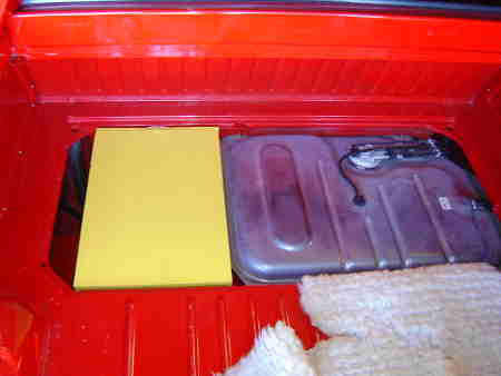
Unlike the 350Z install, this enclosure didn’t have to be pretty at all because it would never be seen.

I learnt a lot from this install that I would take forward to future installs. Namely the 350Z install
350Z Hi-fi Install
Some of Matthew’s advice was to spend in the following fashion:
35% of your budget on speakers, 35% on amplifier, 20% head unit and 10% on sub woofer. This is good advice.
Required Components
Other than the 350Z
- Head unit: Alpine CDE-148EBT From Quality Car Audio
- DIN/DDIN kit: 99-7402 from Quality Car Audio
- Power amplifier: Italian made Audison LRx 5.1MT from Matthew Fung
- Front speakers: Audison AVK6 6.5’s from Matthew Fung
- Rear speakers: Existing factory from Matthew Fung
- Sub woofers: 2 x Alpine SWR-12D4 From Quality Car Audio. One of the reasons for two sub woofers was appearance.
- Sub woofer box: Fabricated with some old 19mm MDF cover sheets that have been in my garage since I left the carpentry trade about 15 years ago.
- Square drive (because they are far superior to posi) super screws
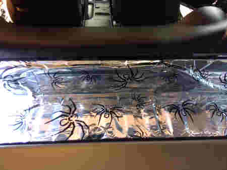
- Sound deadening: Single layer of Soundstream Deathmat from HyperDrive. Once finished about 15kg will be applied to floors, both front and boot and front doors.
- In-line fuse block: 80amp from JayCar
- Battery terminals: from JayCar
- Power cable: 8m of STINGER SPW14TR 4 AWG GAUGE from Ebay
- Speaker cable: Stinger SHW512B 100 ft Roll of HPM 12 Gauge Matte Blue Car Speaker Wire run to all speakers from Ebay
- RCA cables: 3 x Stinger SI8217 Audio RCA Interconnect Cable 2 Channels 8000 Series 17 ft from Ebay
- Internet of course
- Carbon fiber vinyl wrap
- Front speaker mounts: Rubber drain pipe transitions
- Approximately one week labour
Yes I was tempted to skimp on the likes of the power cable, speaker wire, RCA cables because the good ones are much dearer than the cheap ones. This is where you really get what you pay for. If you want to produce a great result, aim for the best you can get here. A few hundred dollars really makes a big difference. I’ve used cheaper parts here on previous installs and the overall difference is very noticeable. It also give you room to upgrade components in the future without having to run all your wires again which is where most of the install time gets sucked up.
Day One
Design and Construct Sub Woofer Enclosure
Generally speaking if you are running two of the exact same sub woofers in the same air space you can just combine the air spaces, but if you swap one of the sub woofers for one that behaves differently, then you are likely to run into issues where the sound waves interfere with each other. Also if you have a sub woofer enclosure that has an air space for each sub woofer you also get bracing for free from the divider. Bracing is all about making the enclosure more rigid so that the sound waves don’t cause the casing to vibrate/move with the waves more than it should. The more rigid you can make the enclosure the more you help the enclosure do what it’s designed to do… produce accurate low frequencies.

I chose to have one enclosure with two separate air spaces, thus providing a rigid casing. There are three distinct volume calculations here.
- One for the main air space
- One for the arch way (Looks like a ‘D’ rotated 90° counter clockwise) you can see cut in the rear of the enclosure
- The space behind the rear of the main enclosure. This had to be done to accommodate the cast aluminium frame of the SWR-12D4.
I also allowed for adjustment in air space with the two ends of the enclosure, as they could be moved in or out depending on whether I needed more or less air space. As you can see in the image above, the rear and the front of the enclosure have tapered cuts down toward the bottom of the enclosure. These tapered cuts were made once A) the box had been constructed, B) the ends had been adjusted and fixed in place and C) I was certain of the internal air space.
All joints are wood glued and sealed with an acrylic sealant. Solvent based sealants can play havoc with some of the sub woofer internals, thus causing premature failure. The screws are varying lengths depending on the angle of the join. All screw holes were pre-drilled into the initial MDF that needs to be retained with the diameter of the thread, so that the thread doesn’t grip onto the MDF being retained. Then the MDF that the screws actually bite into are pre-drilled with a bit the diameter of the shank (which is a little smaller than the thread). If you don’t do this second part, the MDF will just split which means very little grip and essentially a very weak joint.
All screws were countersunk with a… countersink bit. This is done so that when you cover the box in your chosen covering, it all appears flat. Two circular holes cut with jig saw. The holes that the speaker cable passes through are also sealed with acrylic sealant.
I also chose not to use terminals on the sub woofer enclosure to fix speaker wires to, but rather run the speaker wires straight from the power amplifier to the sub woofer, thus removing one of the couplings. The sub woofer enclosure can still be disconnected at the power amplifier and at the speaker. If you’re planning on swapping sub woofers in and out frequently,
As I’m a carpenter by trade (from aprx 1990 – 2000), this construction was trivial.
For those of you unfamiliar with the 350Z, this is what the target space looks like (plan view) with the dimensions:
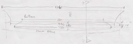
You’ll also notice the cross section arrows. They should actually be facing the other direction. The A:A section is the below image in reverse. If I was to go full width with the enclosure, it wouldn’t be able to be installed as the rear hatch opening is considerably narrower than the enclosures target location. It ends up being just over 100mm gap on each side of the enclosure once installed. I just fill this space with plumbers foam pipe lagging which actually looks fine. There is also a small gap in front of the enclosure (between enclosure and rear speakers) and behind it (between enclosure and strut brace). I’ve just pushed 12mm black PEF rod down the gap and it again looks fine. One of the rules in carpentry is, if you can’t hide a transition, then emphasis it. That’s what we’ve done with these gaps. The enclosure doesn’t need to be fixed in place in case of head on collision, as it can’t move forward but can tilt forward a little, but as the roof is too low to allow it to move forward far, it’s safe. Just make sure those huge sub woofers are well fixed as they would be like canon balls in an accident.
Volume Calculations
The gross internal target volume for the sub woofer was 0.85 ft³. It’s range is 0.23 ft³ both ways. I ended up being just below 0.85 ft³. So I was happy.
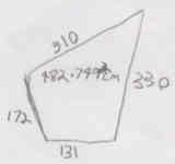
- For the main air space, that’s the largest one. I just worked out the area of the quadrilateral (bottom, front, top, rear) then multiply by the depth. All in cm’s, then convert cm³ to ft³. As I’m lazy, the easiest way is to just throw your values into the calculator here or here. These dimensions are all internal and specified in mm unless stated otherwise.

- For the semi-circle (‘D’ rotated 90° counter clockwise) it’s just πr2/2 for the area then multiplied by the depth of 1.9cm
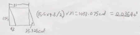
- The following was the calculation for the triangle behind the ‘D’. this is also used to mount the power amplifier. The outer panel here carries across two of these internal spaces. Hope that makes sense? You’ll see an image below anyway of how the power amplifier is mounted on the rear of the enclosure. I also had the very rear panel of the enclosure over-hang the internal dimension by about 50mm. This was so that I could mount some LED strip lighting if I wanted to. The Audison LRx 5.1MT has it’s logo light up which has for now satisfied my geek addiction for LED mood lighting.

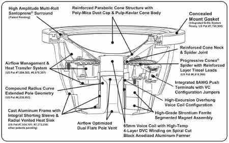
SWR-12D4 Dimensions

SWR-12D4 Design
Day Two
Just more of the same thing plus fitment and making small adjustments. I found that by draping a towel over the rear strut brace and just sliding the enclosure over it and tilting it forward it’d just slot into place nicely.
Day Three
Removal of Internals
Removed all the internal panels that I’d need in order to run cables and apply sound deadening. I numbered each piece I pulled off in order, so that it was easier to work out the re-fit order when the time came. I also mask any plugs or screws etc to the panel so they don’t get lost.
- Remove center console
- Remove panels to get to rear speakers and to run power cable and speaker wires. I also decided to make use of the empty space which is about 2 ft³ behind the drivers seat. For now this is still left open. I’m looking around wreckers for another cubby-hole like the one behind the passenger seat, as they are identical. This will allow me to claim back the space that we’ve lost due to the enclosure going into the limited boot space.
- Removed door sill panels and kick panels. Both of which can be pulled off gently.
- Remove seats. Also followed the sequence in this post to reset the windows going all the way up.
Once I was done with the full install and started the car, the Engine Management Light (EML) came on. This will continue to happen until you reset it. First thing to do though is find out what the fault is if there is one. Follow the sequence of events here. Diagnose the fault code based on the flashes detailed here and here. My code ended up being “P0000” (No Self Diagnostic Failure Indicated). That’s:
10 (0) Long Blink
10 (0) Short Blinks
10 (0) Short Blinks
10 (0) Short Blinks
So I reseted the ECU and I was done.
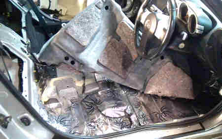
Apply Sound Deadening
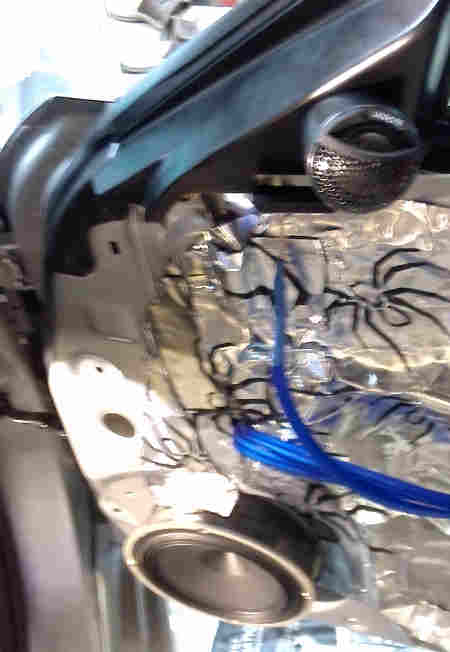
The 350Z’s have a lot of road noise by default. If you want to keep that out so that it doesn’t interfere with your new sounds and keep your sounds inside the car it can be a good idea to apply this liberally. Plus it’s a good time to do this when you have most of your internal panels removed. I’ve found that it made quite a big difference. The sounds are barely audible outside the vehicle even when played at a modest level. When cranked, you can still feel the low frequencies outside more than you can hear them. Believe it or not, that includes the lower frequencies. I applied this a little higher than you can see in the below image. All the rattles you hear in a lot of vehicles with large sub woofer setups are gone. This means the low frequencies are not loosing energy in the panels but are instead going into the cabin space. Which is exactly where we want them.
Day Four
Power from Battery to Power Amplifier
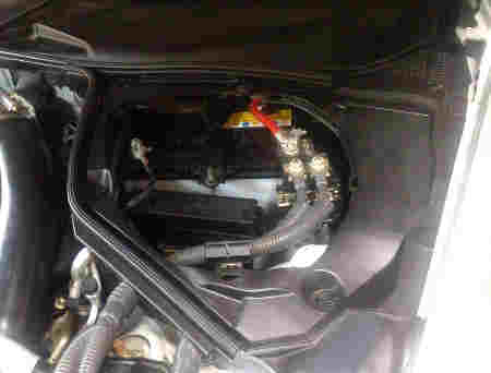
Run power cable from battery through firewall to boot of car where amplifier will sit. This link shows a left hand drive 350Z. For right hand drive Z’s, it’s pretty similar.
Run RCA Leads
from front console to where sub woofer enclosure will live. Careful to keep speaker and RCA leads as far away from power cables as possible to reduce interference.
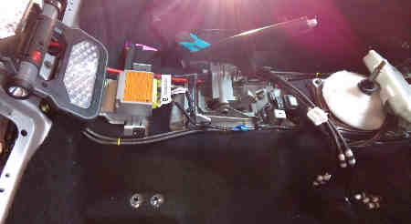
Here you can see the power cable on the left of the drive-shaft tunnel (top of image) and the three RCA leads on the right of the drive-shaft tunnel (bottom of image) zip-tied together and passing through the body just behind where the carpet finishes. You can also see the RCA lead ends looped around the gear stick in the image waiting to be plugged into the new head unit once installed.
Also notice the fold-out work light far left of the image. This is cordless and has magnets on the rear of both LED panels and the middle shaft. The LED panels can be pivoted around the shaft. This is one of the most handy work lights I’ve ever used. It also has a torch light in the middle shaft. This can be run with A) one panel running, B) two panels running, C) just the torch light running. It’s rechargeable and seems to run for as long as I need it each day. I think it’s supposed to run for three hours with only one panel running, but it seemed to run for longer than that. $30 from bunnings.
Run Speaker Wires
All except front left door and sub woofers.
For the front speakers, the hardest part of just about the entire install is getting the 12 gauge speaker wire through the plastic door harness without joiners. This post provided the detail I needed. Previous car hi-fi installs have been similar in that this task has been the most frustrating. I started with the right door (drivers door) which is harder than the passenger door for several reasons.
- There is next to no visibility from underneath the steering wheel looking at where the speaker wire must pass through the plastic harness
- The plastic harness has a greater population of used pins that you have to be very careful not to hit with your knife or drill. I used both tools.
The other thing to keep in mind is that the plastic harness that clicks into place on the car body must go in top first from the inside, not bottom first. This cost me a bit of time (I bent the metal retainer out of shape because I put bottom in first) and I ended up coming back to the driver side after I’d done the passenger side successfully and learnt a few more tricks.
For the front speakers, I ran the speaker wires down the door sills right next to the plastic clips that hold the sill covers on. Then through the holes at the back of the sill and through into the boot near where the power amplifier would be mounted.
I also ran 12 gauge wire for the rear speakers. There are plenty of holes to thread them through and keep them well concealed. Keeping in mind that they need to stay as far away from power cables as possible.
Factory Speaker Wire Colours
I took note of factory speaker wire colours in case I needed them later. I didn’t, but here they are anyway for anyone needing them:
Front Left
- Red with silver loops
- Blue with silver loops
Front Right: Didn’t capture these
Rear Left
- Light green with silver loops
- Light brown with dark brown stripes
Rear Right
- Light orange with silver loops
- Black and pink stripes with silver loops
Day Five
Fit Tweeters
See the image on Day Six for how the tweeter looks mounted. The small plastic triangle panel that the tweeter is fixed to from memory needs to be pulled in toward the car where it meets the window pane and then slid down. Mine had an existing round grill that looked like a tweeter was mounted underneath, but all it was was a grill. I drilled a hole just big enough to pass the tweeters existing wire through it. At this stage I’ve used double sided sponge tape. The tweeters are fairly heavy so we’ll wait and see if the tape continues to hold them on. If it doesn’t I’ll have to resort to some glue. Currently it’s been about a week and they’re still staying put. I used some acetone to clean the surface of both the rear of the tweeter and the area that it was going to be fixed to. Just be careful with this though, as it will start to melt the plastic, so make sure you only do it where it’s not going to be seen.
As you can see in the image, no wires are visible and it’s a good position for the sound stage. I’ve got the crossovers set to the highest gain for the tweeters. I thought this may have been to much, but it seems perfect. The lower frequencies are surprisingly well handled by the Audison AVK6 6.5″ drivers.
Run Speaker Wire to Left Front Door
Similar to the right door.
Day Six
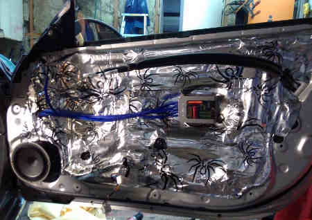
Apply Sound Deadening to Side Doors
A lot of road noise comes in the doors on the 350Z’s. Also with your hi-fi setup, you’d loose a lot of energy through your doors. Applying sound deadening liberally to the doors as well as the floors stops a lot of this. It’ll also kill any rattles you may have had otherwise.
Fit Front Speakers with Crossovers
There is a sunken space where I fixed my crossovers. I soldered and crimped terminals to the speaker wires that get screwed to the crossover. I soldered and applied heat-shrink sleeving to the tweeter wires / 12 gauge wire junction.
Fit Rear Speakers
I was using the existing factory speakers as they don’t really matter that much. Why don’t they matter much? Most of your sound stage should be coming from the front of you.
In my case there were no signs of which speaker terminal was positive or negative. The best way to work this out is to use a 9v battery and touch wires from the batteries + and – terminals to each of the speakers terminals. if the speaker pops out slightly when connected, it means you’ve connected the batteries + to the speakers +. If the speaker pops in slightly when connected, it means you’ve connected the batteries + to the speakers -. This way you can tell which terminal you should connect your designated positive speaker wire. This method doesn’t harm your speaker as the voltage is too low.
Day Seven
Install Head Unit
Most of the steps you would need are here.
Fit DIN/DDIN kit 99-7402 to the dash assembly. As the CDE-148EBT is a single DIN unit, we get some space back in the form of another compartment below the head unit.
The Alpine CDE-148EBT comes with a harness. I only needed to solder -> heat shrink on the following harness wires to the existing wires. The existing wires were all factory labelled with tags. This was obviously very helpful. I had already located a wiring guide for this operation that I would not now need. Strange thing was with the guide that the colours were incorrect for my Z.
- Orange (head unit illumination)
- Red (ignition)
- Yellow (battery)
- Black (ground) just replaced existing ground wire
- Blue/white (remote turn on, supplies 12v to power amp to tell it to turn on when head unit is on) I missed this one and had to pull the console out again and connect it. I go through this in day eight.
Connect Aux in, USB extension lead, all six RCA’s.
There are a lot of wires behind the head unit and it can be a bit tricky getting everything back in. Be gentle and patient.
Re-fit Seats and Some Panels
Self explanatory.
Apply Sound Deadening
Around where sub woofer enclosure is going to live. I applied it to the sides also.
Fit 80 amp In-line Fuse
I fitted the fuse block about 150mm from the battery. The end of the in-line fuse block is just visible in the below image.
Install Sub Woofer Box

Fit Sub Woofers
If you plan on swapping your subs in and out a bit then I’d advise using the likes of these inserts to screw into. Screw these into your MDF then screw into them:

It was about here that I realised that I should have gone with the SWR-12D2 (the 2 ohm version) sub woofers. As I hadn’t actually used the sub woofers yet, I’d be able to just exchange the 4 ohm subs with the 2 ohm subs. Quality Car Audio refused to provide an exchange for the still new subs. Both 4 ohm and 2 ohm models where exactly the same price.
Some reading on under-powering sub woofers:
Connected Power Cable to Amplifier
Ran Earth Cable to Bare Metal
Unscrewed a bracket that came through the left side of the car in the spare wheel well and fitted the terminal I had soldered and crimped onto my 4 gauge earth cable between the bracket and the body of the car after I sanded the paint off for good connection. Cranked that bolt up nice and tight.
Connected all Speaker Wires to Power Amplifier
Connected RCA Leads
Test Front and Rear Speakers
Re-install internal panels
Day Eight
Power Amplifier Not Auto Powering On
Take power amp in to be tested as it wouldn’t power on. The car power amplifiers I’d used in the past would turn on when they receive signal from the pre-outs. That’s signal that’s pre-amplified. Turns out a jumper, well a plastic jumper with a single 12v remote turn on from the head unit was needed on the bottom left pin of the power amplifier. So out with the head unit again and run the extra wire. That’s why you want to leave re-fitting of panels as late as possible.
Cleaned up
Charged Battery
Initial Tuning
Power Amplifier
Currently I have the Audison LRx 5.1MT gains set to (where 0 is 0 and 10 is max):
- Fronts: 8
- Rears: 3 (existing very crappy factory speakers)
- mono Sub woofer channel: 8
Head unit
- Turn off internal power amp as it’s not used and helps to reduce power supply interference/noise
- The Alpine CDE-148EBT has a lot of options and features when it comes to tuning your sound. This will keep me busy for a long time I’d say.
Sub Woofer Configuration
- I first tried 2 ohm setup with one speaker as a benchmark because I knew that it was ideal
- I then tried parallel 1 ohm which I don’t think provided enough energy to the sub woofers
- Third configuration I tried was in series 4 ohm which worked quite well.
I’ve also noticed that with the sub woofers pointing forward so I can actually hear them may not have been the best design decision. Especially with two of them running in mono as it affects the sound stage a bit. it probably would have produced a slightly better result if they had of been pointing toward the rear of the car under the strut brace so that the bass could be felt more than heard. In saying that, it’s still early days and I have a lot of tuning to get the levels just right. Also as I didn’t want to remove the spare wheel which sits under the boot base in order to mount the power amplifier under there, one of the only places left would be to mount it on top of the sub woofer enclosure, which although it is rather a good looking piece of hardware. I think 12″ sub woofers look better.

A bit more reading on parallel verses series wiring of your sub woofers.
Mounted Power Amplifier to Rear of Sub Woofer Enclosure

Overall Sound
I’m kind of surprised that I’ve managed to achieve such a truthful sound of my recordings. I wasn’t sure this was possible in a car. Think of studio monitors and that’s what this system reminds me of. All of a sudden many recordings sound bad and the good recordings sound outstanding and produce the emotion that high quality music (recording, mix, mastering) is renowned for. For example my personal recordings that I did a few years ago sound amazing as I had the help from one of New Zealand’s best sound engineers / producers (Ian McAllister).
I think also the fact that I didn’t take any short-cuts that I’m aware of? It’s all the small details that add up as well as using great components.
Ongoing
Hunting down boot carpet for reduced space. The factory carpet in the Z is not actually carpet but just felt. So I’m going to get some real carpet with the ‘Z’ embroidered into it. There are a few places that actually supply this.


